Garrattfan's Modelrailroading Pages

NS 7000 class
Chassis assembly
- Introduction
- History of the 7000 Class
- Inventory of the kit
- Instruction manual
- Chassis
- Chassis painting
- Chassis assembly
- Superstructure
- Superstructure detailing
- Gallery unpainted
- Painting
- Disaster
- Painting continued
- Final Assembly
- Gallery completed loco
- Evaluation and conclusion
- Recommended resources

In het Nederlands
In parallel with the frame assembly I also worked on the superstructure. This brought some variation in the work and it had the practical side of making it possible to match chassis and superstructure to check the fit and the fastening.
In 2007 I had made my latest attempt to complete the loco. Work had stalled for some time. For one I was working on a Shay as well. And second I had painted almost everything when I dropped the box with the loco. It send the parts sprawling and wreaked havoc among the painted parts. I had no choice but to remove all paint and start all over again. I was so discouraged that I left it to rot for some time. Then I realised I would forever loose this hobby if I would not complete this loco. The success of the completion of the Shay and various other small projects had been most encouraging. So in May 2008 I took a deep breath and set out to complete the NS 7000. Why do I tell this? Well, just to show beginners in the hobby that projects sometimes turn into a struggle. And to tell this is perfectly normal. I always say there's more than "P" to "P"roject:
Patience, Perseverance, Practise plus Precision Produce Perfect Projects
This page is an amalgamation of the various attempts to get the painted chassis together. |
|
The frame assy consist of many and very small parts. |
|
| I've optimized the frame assy before painting. I have written an article in Dutch which was published in the Dutch Railmagazine. | |
 |
The frame assembly starts with inserting the gearbox and geared axle in the frames. |
 |
The Romford wheels are put in place and secured with the characteristic small slotted hollow nut. The wheels are easily quartered: Romford have square axle holes. The right hand side of the locomotive is one quarter ahead of the left hand side. That means: if the crank on the left hand side is up (twelve o'clock), the crank on the right hand side should point forward (three o'clock). |
 |
I adapted a screwdriver to work with the slotted Romford nuts. Markits offer a special axle nut screwdriver. I bought it some years later and found it to work considerably better.
M89 MRAX/SCDVR in the 2013 catalogue*) in page 15. Costs about £5.
*) Their 2013 catalogue was their most recent one in early 2021 |
 |
The completed motion: bracket plus crossheads and crosshead slides, drive rods and both sets of valve gear. It weighs just a few grams but consists of around 40 parts. |
 |
You need to be an octopus to fit the entire motion in place. |
 |
The axle bearings have a tight fit in the U-shaped openings in the frame plates. I simply put the bearings in and glued them in place. It never so much as occurred to me that the frames could be warped, if ever so slightly, or the frame holes could be out of alignment. And by sheer coincidence it worked out well. Or maybe any error was relieved by the huge play in the oversized holes of the coupling rods.
As noted earlier I could better have built the chassis in a chassis jig like the one from Poppy's Woodtech. |
 |
The leading bogie is actually sprung. The brass collar is moved over the thread of the bolt and the spring placed. Be extremely cautious in the next moves where you put the spring under pressure. It flies a surprising long way if it escapes. |
 |
Put the washer in place and gently press it down. |
 |
While holding this washer with the tweezers I put the bogie in place. Note the hole allows the bogie to move sideways. I do not remember whether this hole already had this form or whether I made it this way but anyway the bogie needs a little sideplay. |
 |
Place the captive nut and secure it with a bit of glue or thread locker. |
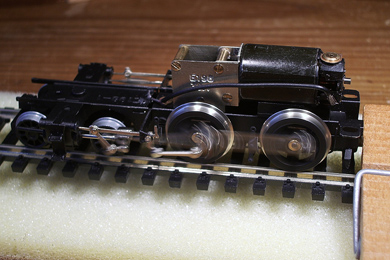
The frame on its wheels. It is not able to run yet as the brass bolts on the motion bracket and the crosshead still need to be shortened
|
|
 |
The bottom plate is screwed into place with two stubby flat brass screws. |
 |
 |
| Shorten the brass bolts on the motion bracket and crosshead and file them flush. Secure them with a bit of glue or thread lock. | |
 |
 |
| The electric leads are soldered. | |
 |
And then, at last, it is time to do the trial running. Now iron out any problems that may have escaped your attention until now. All binding however slight it may be must be eliminated. |
 |
 |
 |
 |
A view from all sides of the completed chassis. Note that I attached the electric wire over the motor. This makes it easier to slide the superstructure over the motor without the wire getting in the way. I used a piece of black tape both to fix it in place as well as to hide it from sight.
|
|
|
And finally some moving footage of the completed chassis. |
|


Sign my
GuestBook